NotePAC-III-PRO-V triple screen - 2 slot - Xeon powered portable. Now with battery option.

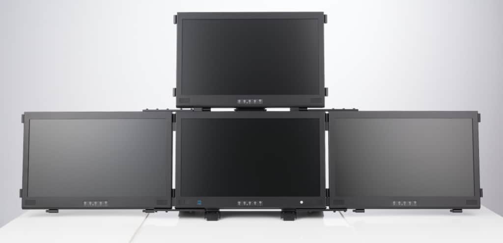
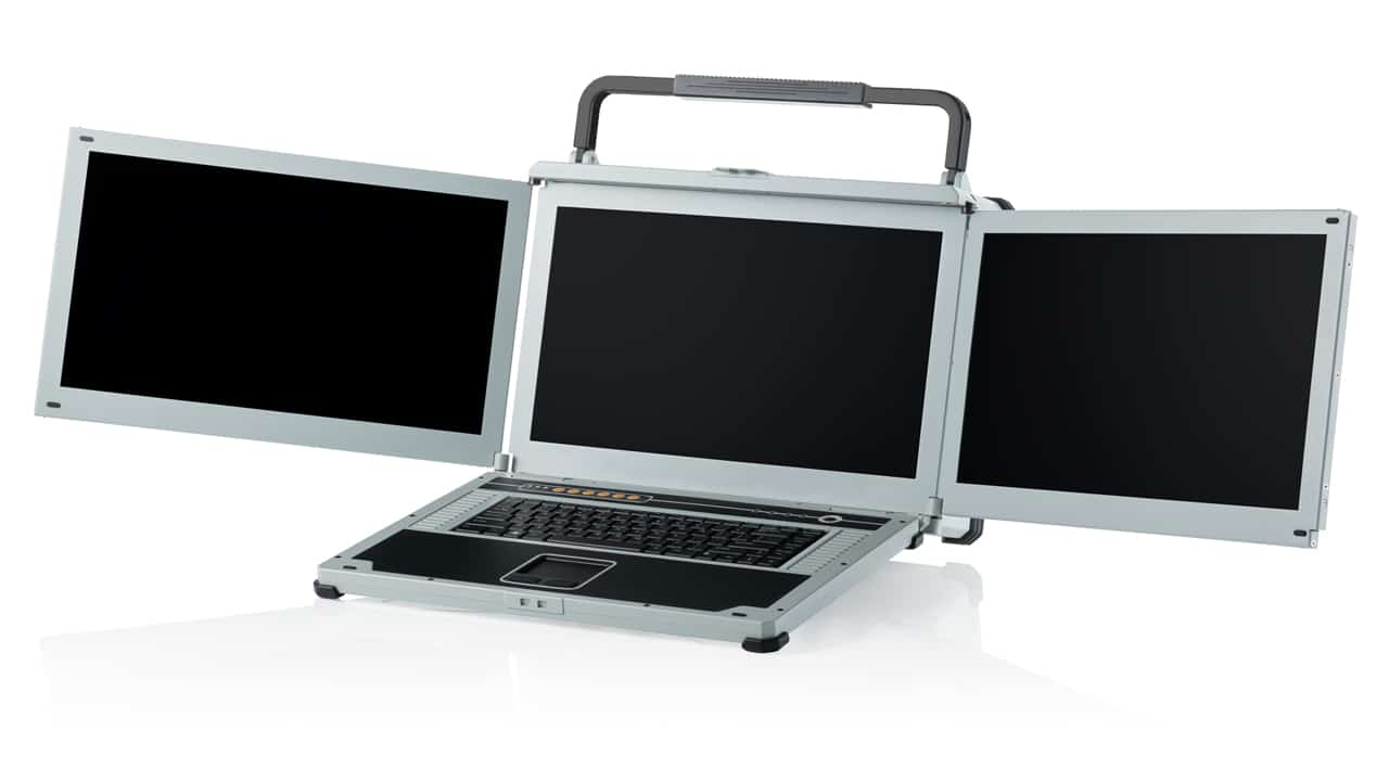
Deployable Video Processing Laptop

Rugged triple screen Xeon portable with video capture card

Portable video system for rugged deployment

Video editing rugged laptop

Server class Ethernet I/o on rear panel

Triple screen rugged portable

Video capture laptop

Triple screen rugged laptop

NotePAC-III-PRO-V

Vertical triple screen portable

NotePAC-III-PRO

Rugged laptop – triple screen

NotePAC-III-SC

Rugged laptop – Special configuration


Triple screen rugged laptop with video capture hardware


COTS - Commercial, off the shelf computers

Video capture hardware solution

Many security and surveillance missions rely on video. They need to monitor, capture, and disseminate video feeds. If a picture tells a thousand words, then a video is a library full of information. Capturing, processing, and evaluating video footage in a mobile environment can be challenging. Portexa now has a video capture laptop that makes deployed information gathering and video analysis a reality.

The NotePAC-III is a triple screen portable laptop. Machined from aluminum, and with high-end graphics and a video capture card designed for use in theatre. The NotePAC-III has passed Mil-Std 461 (EMC/EMI), DTE-901E (Shock/Torpedo Strike) and 810G (environmental).

“We are proud to have helped develop this excellent deployed solution.”

Three screen notebook with expansion slots

Technical specifications:

Deployable Video Editing Laptop:

Small and light enough to travel with you and go in an airline overhead bin, the NotePAC-III packs a lot of power into its robust chassis.  A 16 core Intel Xeon and up to 512GB of RAM means you can run more virtual machines than most people need.  Four 7.6TB removable SSD drives give you space for video files and other storage.  If that’s not enough, you can attach a NAS (Network-attached storage) through one of the two 10G fiber ports, and still have multiple Gigabit ports free.

Intel Xeon 16 Core Processor

512GB RAM

30TB removable SSD storage 

The standard capture card supports H.264 hardware compression for a multitude of formats:

Max  FPS: 1920×1200p@60/50fps in 1920×1200p@30/25fps out

1920×1080p@60/50fps in 1920×1080p@60/50fps out

Video Input:

1×HDMI, 1×DVI-I, 1×YPbPr, 1×SDI, 1×CVBS, 1×S-Video

Video RAW data resolution

1920×1200p@30/25/24fps

1920×1080p@60/50fps

1920×1080p@30/25/24fps

1920×1080i@60/50fps

1280×720p@60/50fps

1280×1024p@60fps

1280×960p@60fps

1024×768p@60fps

800×600p@60fps

640×480p@60fps

720×480p@60fps

720×576p@50fps

720×480i@60fps

720×576i@50fps

Audio Inputs:

1×SDI Embedded Audio, 1×HDMI Embedded Audio, A Pair of RCA Audio Connector (Audio L/R Through Component Cable) Stereo / 16-bit / 32 ~ 48KHz


Recording Video Resolution

1920×1200p@30/25/24fps

1920×1080p@60/50fps

1920×1080p@30/25/24fps

1920×1080i@60/50fps

1280×720p@60/50fps

1280×1024p@60fps

1280×960p@60fps

1024×768p@60fps

800×600p@60fps

640×480p@60fps

720×480p@60fps

720×576p@50fps

720×480i@60fps

720×576i@50fps

The computer video card is an Nvidia Quadro P4000, which is the world’s most powerful single-slot professional video card.  It has 8GB of DDR5 RAM and can process 5.2 TFLOPS Single Precision floating point 32 bit.  There is a custom cooling vent for the video card’s fan to ensure maximum performance under load.  This hardware makes video editing feel seamless and productive.

Three 17.1” HD monitors unfold to give a 5760 x 1080 display.  High-quality friction hinges allow the displays to be adjusted for rake and the outer displays tilted in for optimum ergonomics.

The backlit keyboard allows use in low-light conditions such as the CIC (Combat Information Center) or other C4ISR operations center.  A touchpad is provided, and there is a conveniently placed USB port for mouse operation for those that prefer it.


More information can be found at NOTEPAC-III

Four-display transportable workstation


Triple screen deployable workstation closed.

Three screen portable workstation with three multi-touch displays


Massive expansion portable workstation with touch screens

MegaPAC L1, L2 & L3

Now with PCT Multi-touch screens


24" display portable touch screen workstation

monster cooling workstation system

Dual Screen touch-screen portable server / graphics workstation

Dual display with secondary display on top - multi-touch

Multi-touch portable workstations

The latest touch screen technology is now available on large deployable workstation screens.  The ACME MegaPAC is now available with Projected Capacitive Touch screens.  Single, dual and triple screen workstations are available, and whichever system suits your needs, all screens support multi-touch input.

Almost everyone today is using touch-enabled mobile devices, tablet devices, or laptops on a daily basis. Multi-touch capabilities are merely table stakes now in mobile computing devices, and the gaming or signage industries.

Touch screens on mobile devices were revolutionized in 2007 when Apple released the first iPhone.  Of course, Apple did not invent the technology, but it was the first time it was made available on a mass-market device.  What made the iPhone tech interface different?  Gestures, pinch and reverse pinch- to zoom out and in, swiping, etc.  Before that, touch devices were restricted to single points (like clicks).

Now multi-touch gestures are available on the 24” displays of the MegaPAC portable workstation. 

If we take a look at the original touch-screen technologies we can trace the evolution and understand the technology behind multi-touch displays:


Some of the earliest touch displays used infra-red beams of light in a grid.  Sensors would ordinarily ‘see’ the beam, but when a finger was placed on the display, it broke one or more beams, giving the touch screen controller an X & Y coordinate for the ‘break’ and provide a ‘touch’ input.  This technology is still in use as it allows the display glass to be made really tough, unlike the restive and capacitive alternatives.

24" display portable touch screen workstation

IR Touch screens are suitable when a harsh environment (for example one that will be used by the public) is expected.  They are:


  • Vandal-proof, wear-resistant
  • Maintenance-free, longer life expectancy
  • Versatile touch object (Pointer or finger or glove)
  • Super transparency (no membranes between the display and user)
  • Operable in various light conditions, indoors and outdoors

These sorts of touch displays are usually found in POS, ATM, Kiosks, gaming machines, and industrial control systems.

Touch Screen Technologies

Resistive touch screenResistive touch screens

Resistive touch screens work by sensing the closing of a contact between two conductive membranes.  There are typically an array of dots, visible upon close inspection, that holds the two membranes apart until the ringer or pointer closes the gap by deforming the membrane.  This highlights one of the advantages of resistive screens over capacitive technologies – the pointing device does not need to be conductive, so a fingernail, a glove or a stylus can all work.  Resistive touch screens can be quite precise and don’t suffer from calibration drift as much as some capacitive screens.

Disadvantages are that there are at least two layers of membrane – typically plastic – between the display and the user, which reduces light output, and therefore reduces brightness.  Over time, the flexible membrane can become fatigued and ‘cloudy’ further reducing display clarity.  The other big disadvantage is that resistive touch screens can only detect a single pressure point – so there are no multi-touch gestures like pinch to zoom.

Surface acoustic wave touch screenSurface acoustic wave

Surface acoustic wave touch screens work by sending an ultrasonic wave (ultra-sound wave) across the surface of the glass.  Sensors detect the reflected wave and in some cases the attenuated wavefront that is caused by the pointer or finger.  This is then translated into an X-Y coordinate for the touchpoint.

Capacitive touch screenTraditional capacitive touch

Otherwise known as surface capacitive – work by detecting a change in capacitance of the field in front of the screen caused by a conductive entity of some sort.  Usually a finger.  Capacitive touch screens are commonly made of two layers – a surface insulator and a transparent conductive layer below it. As the human body is an electrical conductor when the touch panel is touched with a finger the electrostatic field of the panel is distorted.  The touch screen controller then decodes the changes in capacitance and returns a touchpoint to the system.  The advantages are that there is no membrane that needs to flex, so the touch-screen should last longer.  Disadvantages include possible drift over time on large displays, which require periodic re-calibration.  Because the sensor is a glass panel, there is less visual degradation than with resistive screens.

Projective Capacitive Touch Screen TechnologyProjective capacitive touch

Instead of one capacitive sensor, there are many, usually on two layers of transparent conductors.

Projected Capacitive Technology (PCT) is fast becoming one of the most prevalent touch technologies for touchscreens. PCT technology is what allows us to tap, pinch, zoom, and scroll with various gesture controls and using multiple fingers, and can be used in a wide range of applications from consumer devices to commercial products. 


PCT devices identify touch by measuring the capacitance at each addressable electrode in a dual-layer grid. When you touch the surface of a capacitive device, there is a disturbance in its electrical field (capacitance), which allows the device to determine when and where the touchpoint occurred.

PCT technology uses two main types of sensing methods, self-capacitance and mutual capacitance, each having its own advantages and disadvantages. In short, self-capacitance devices offer a higher signal strength and sensitivity to touch but does not support multi-touch (more than 2 touch-points) like mutual-capacitance devices.


“Projected capacitive technologies detect touch by measuring the capacitance at each addressable electrode. When a finger or a conductive stylus approaches an electrode, it disturbs the electromagnetic field and alters the capacitance. This change in capacitance can be measured by the electronics and then converted into X,Y locations that the system can use to detect touch” ( from 3M)


ACME’s addition of PCT technology to the MegaPAC results in a superior portable computing platform with a durable, UHD multi-touch touchscreen. The MegaPAC is a high performance, high-fidelity interactive solution that meets customers’ expanding user interface requirements.


For more information please contact sales@portexa.com 


PCIe Lanes explained

An introduction

PCI Express, PCIe, or Peripheral Component Interconnect Express, can be a somewhat complicated computer specification. When your computer first boots, PCIe is what determines the devices that are attached or plugged into the motherboard. It identifies the links between each device, creates a traffic map, and negotiates the width of each link. This identification of devices and connections uses the same protocol as PCI, so no changes were required when changing from PCI to PCIe in either software or operating systems.

A PCIe connection consists of one or more (up to sixteen, at the moment) data-transmission lanes, connected serially. Each lane consists of two pairs of wires, one for transmitting and one for receiving. There are 1, 4, 8 or 16 lanes in a single PCIe slot – denoted as x1, x4, x8, or x16. This is the difference between PCI connections which are parallel (32-bit or 64-bit bidirectional parallel bus) and PCIe which is basically a serial version of PCI.

If you need a portable computer with expansion slots – see ‘portable computers with expansion slots‘.

PCIe Lanes on a Motherboard`

PCIe Lanes

How do PCIe Lanes work?

PCIe is a multi-layered protocol – the layers being a transaction layer, a data link layer, and a physical layer.  The Data-link layer is sub-divided to include a media access control (MAC) layer.  Each lane consists of two unidirectional differential pairsoperating at 2.5, 5, 8 or 16 Gbit/s, depending on the negotiated capabilities. While on the other hand, transmit and receive are separate differential pairs, adding up to a total of four data wires per lane.

Each lane is an independent connection between the PCI controller of the processor chip-set (Southbridge) or the processor itself (which is almost always the graphics card slot) and the expansion card. Bandwidth scales linearly, so a four-lane connection will have twice the bandwidth of a two-lane connection. Depending on the expansion card’s bandwidth requirements, the slot may need to be sized accordingly.

PCIe connection diagram from How stuff works
From How Stuff Works

A physical PCIe x16 slot can accommodate a x1, x4, x8, or x16 card, and can run a x16 card at x16, x8, x4, or x1. A PCIe x8 slot can accommodate a x1 or x4 or x8 card but cannot fit a x16 card. Just to confuse the matter further, there are different versions of PCIe interface.  It’s also possible that a motherboard may have multiple slot sizes and also different PCIe versions: 1.0a, 1.1, 2.0, 2.1, 3.0, 3.1, 4.0 and coming soon 5.0.  (Link to https://en.wikipedia.org/wiki/PCI_Express#PCI_Express_5.0)

BUS & Theoretical Bandwidth Available

BUS Bandwidth
PCI 1056 MBps
AGP 8x 2.1 GBps
PCIe 1.0 / x4 1 GBps
PCIe 1.0 / x8 2 GBps
PCIe 1.0 / x16 4 GBps
PCIe 2.0 / x4 2 GBps
PCIe 2.0 / x8 4 GBps
PCIe 2.0 / x16 8 GBps
PCIe 3.0 / x1 1.97 GBps
PCIe 3.0 / x4 3.94 GBps
PCIe 3.0 / x8 7.88 GBps
PCIe 3.0 / x16 15.75 GBps
PCIe 4.0 / x1 3.94 GBps
PCIe 4.0 / x4 7.88 GBps
PCIe 4.0 / x8 15.75 GBps
PCIe 4.0 / x16 31.5 GBps
PCIe 5.0 / x16

Firewire 400/800

63 GBps

400/800 Mbps

USB 1.0 12 Mbps
USB 2.0 480 Mbps
USB 3.0 4.8 Gbps
USB 3.1 10 Gbps​
Gigabit Ethernet 1 Gbps
IDE (ATA 100) 800 MBps
IDE (ATA 133) 1064 MBps
SATA 1.5 Gbps
SATA II 3 Gbps
SATA III 6 Gbps

Why do PCIe Lanes matter?

Functions your CPU’s PCIe Lanes Control:

  • Onboard Video
  • PCIe 3.0 x16 Slot (usually for video card)
  • 2/U.2 (on some Enthusiast Boards)
  • LAN (on some Enthusiast Boards)

Other functions use your CHIPSET’s PCIe bus lanes. Functions CHIPSET’s PCIe Lanes control may control:

  • SATA hard drives
  • Onboard Sound
  • Onboard RAID
  • Onboard Network Controller/LAN
  • All PCIe slots except the first one
  • Thunderbolt
  • 2/U.2

Quoted amounts of PCIe bandwidth required by individual components:

  • 8-16 Lanes – x16 PCIe Video Cards (Each)
  • 8-16 Lanes – Other Specialized PCIe Cards
  • 4 Lanes – M.2 Drive
  • 4 Lanes – Thunderbolt (uses 4 lanes PCIe 3.0)
  • 4 Lanes – Hardware Based RAID Controllers
  • 2 Lanes (Each) – SSD Drives
  • 2 Lanes – USB 3.1 (Gen. 2)
  • 1 Lane – USB 3.0 (USB 3.1 Gen. 1)
  • 1 Lane – Sound
  • 1 Lane – Network Controllers

Which chips have the most PCIe lanes?

Different chips support different numbers of PCIe lanes. For example: Intel Core i5 or i7-8700K or i9-8950HK have up to 1×16, 2×8, 1×8+2×4 with a maximum of 16 PCIe lanes.  In addition, the 6850K and up i7’s have 40 lanes. The Intel Xeon E5-4669 v4 has a maximum of 40 PCIe lanes at PCIe 3.0, whereas the E7-8894 v4 has ‘only’ 32 lanes (per processor). AMD has upped the ante with their EPYC CPU’s – they have 128 PCIe lanes 3.0.

In the tech industry today, what makes this really complicated is that motherboard manufacturers have to make their motherboards support a range of processors which may have different numbers of PCIe lanes supported.  So a motherboard using an i7-6850K chip may have the capability to address multiple slots at x16, whereas with a ‘lesser’ chip ie. i7-8700K may be fewer lanes available, with only one slot being x16.  Just to complicate things further, NVME and other types of expansions require PCIe lanes. With NVME being a must-have feature for a modern motherboard, there are now even fewer lanes available to the expansion slots. 

Working out how to get the most out of a motherboard in terms of application performance becomes even harder when you need to choose how to connect to the real world.  PCIe lane allocation can make or break the performance of high-speed boards like RAID controllers when they are operating near-maximum capacity (which is now possible due to fast SSD storage). 

While there are some non-PCIe interface options being explored by computer manufacturers, they would also require major hardware changes. All in all, PCIe looks to remain crucial for a while longer, even while the form factor of the connection continues to evolve.

Links:

Adam Savage’s Tested.com did a nice explanation of PCIe speeds and comparison with Thunderbolt.

Anandtech did a nice writeup of the Z170 chipset and the trade-offs that board manufacturers have to make when selecting how to configure the PCH

And here is a nice post explaining how to convert GT/s to Gbps